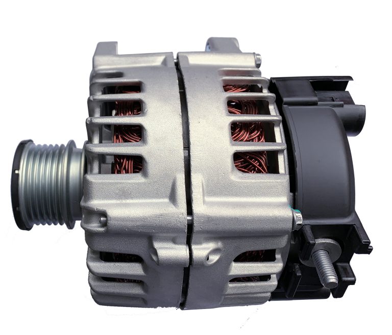
The alternator’s operation is a masterclass in applied physics, blending mechanics and electromagnetism to power your car. For gearheads and engineers, its inner workings reveal the elegance of energy conversion—let’s dive into the science.
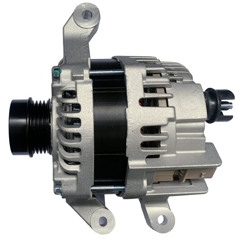
It begins with mechanical energy. The engine’s crankshaft, spinning at 600-6,000 RPM, drives a belt connected to the alternator’s pulley. A 2:1 or 3:1 ratio accelerates the rotor to 1,200-18,000 RPM, delivering torque (5-10 Nm). This rotational motion is the alternator’s fuel, governed by Newton’s laws—force equals mass times acceleration.
Electromagnetism takes over inside. The rotor, an electromagnet energized by 2-5 amps from the battery via slip rings, creates a magnetic field (B-field). Spinning within the stator—a three-phase coil—its flux changes over time. Faraday’s law (ε = -dΦ/dt) dictates that this induces voltage in the stator, peaking at 20-30 volts AC unloaded. Each phase, offset by 120 degrees, ensures continuous power, per sinusoidal wave physics.
Lenz’s law explains the rectifier’s role. As AC flows, diodes resist reverse current, converting it to DC at 12-14 volts. Efficiency losses—20-30%—manifest as heat, dissipated by the alternator’s fan and aluminum housing. The voltage regulator, using feedback control, adjusts field current to maintain output, a nod to Ohm’s law (V = IR).
For nerds, alternator output scales with RPM and field strength: P = V × I. At 2,000 RPM, a 100-amp unit delivers 1,400 watts. Belt friction, bearing drag, and diode resistance sap some power, but modern designs hit 80% efficiency. Testing this—say, with a dynamometer—confirms the physics in action.
This interplay of motion and magnetism keeps your car alive. It’s physics at work—practical, precise, and powerful.